When your good old back’s not up to it anymore, let a windlass do the donkey work
It’s strange how much difficulty we owners of older boats have in finding $500 to $1,000 to replace an old kitchen appliance or to provide new furniture for the den … and how little difficulty we have spending it on new stuff for the boat … especially when priorities change.

Thus it was with our Bluebonnet, a 20-year-old Valiant 32. An anchor windlass was something we had mentioned in passing several times, but it wasn’t even considered when we upgraded her. We had never owned a boat with a windlass and had always raised our anchor by hand (or rather, by back) on previous boats. Once our 30-something-year-old son remarked after breaking loose and raising our 35-pound Delta: “Boy, that was set well, I really had to grunt to get it up.” But such comments sailed over my head until last fall.
We were involved in a household painting project. When I bent over to pick up a gallon of paint, it felt as if someone hit me with a baseball bat across my kidneys. A trip to the doctor revealed that I had a sprain. I was told that my back showed my age, and I should take care of it with exercise and common sense.
Suddenly the windlass went to the top of Bluebonnet‘s list … above the autopilot that was previously on top. My wife, Jeanette, and I are planning several cruises. As our plans call for living on the hook much of the time, our anchoring equipment was re-evaluated. After all, if I couldn’t get the anchor up, it would have to stay down. In most sailing skills, Jeanette is my equal except where significant upper-body strength is required.
Many questions
The research started. What kind? Electric or manual? Horizontal or vertical? How big? The results were as expected: there is no “right” windlass. As with everything on a boat, it’s a compromise.
The first choice was between manual and electric. The cost of a manual windlass was comparable to an electric windlass of the same capacity. A “Waldenese” approach to sailing had always appealed to me, thus the simplicity of a manual windlass had much to offer. Installation is much simpler: no heavy expensive wiring to run nor solenoids and foot switches to buy and install. The cost of these items can add hundreds of dollars to the cost of the windlass itself. Battery capacity has to be re-assessed and possibly increased, too.
Cruising classics (by Hiscock, Pardey, Roth, and others) extolled the advantages of the manual windlass. Against these arguments was the obvious ease of operation of an electric windlass. Many electric windlasses can be operated manually in an emergency. In most cases, the engine will be running when you’re raising or lowering the anchor, and the battery drain is compensated for by the alternator output. The added safety factor of an electric windlass is that it’s much quicker to re-anchor if winds shift. What confirmed my decision to go with an electric windlass was a statement in a book by a well-known and respected cruising writer who said that on his boat, comparable in size to ours, he had used his manual windlass only twice in eight years. He found the manual windlass to be so slow he just pulled it up by hand. I thought: “So why have it?”
Easier answer
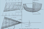
The question of horizontal or vertical gypsy windlass was easier. As the stem of a Valiant 32 is about 8 inches higher than the foredeck where the windlass would be installed, a vertical windlass would need be mounted on a fairly high pedestal to get the proper angle of lead to the bow roller. With a horizontal windlass, this problem is not as critical and can be solved much more easily. The top of the gypsy, where the rode leads off a horizontal windlass, is already several inches higher than on a vertical windlass.
In many applications, a vertical windlass has several advantages. It takes up less space on the foredeck, although the below-decks motor does intrude into the anchor locker. Some horizontal windlasses also have their motors mounted beneath the deck. These are usually of a “worm and gear” construction, which has considerably more internal friction and a much higher current drain. After considering all factors, a horizontal windlass was the choice.
Size was a difficult decision. As a do-it-yourselfer, I tend to overbuild things, so my choices are frequently overkill. Offshore cruisers advocate heavy ground tackle. As the first line of protection for their home and possessions, this is a logical and proper approach. The manufacturer of the Maxwell windlass recommends that the windlass have the reserve capacity to handle three times the weight of the anchor and rode. If I were preparing for an extended cruise to the Caribbean, I would have heavier ground tackle than I presently have, which is a 35-pound Delta and a 25-pound CQR as primary bow anchors. I might also go to all-chain rode instead of a mixed rode of chain and three-strand nylon.
What size?
So should I buy a windlass to fit the ground tackle we have now and our present cruising plans? Or should I get one that would be adequate for any future far-flung dreams? Three times the weight of an anchor and rode for offshore cruising would be in the 1,000-pound range. Some 300 feet of 1/4-inch high-test chain at 0.74 pounds per foot weighs 222 pounds. Add 45 pounds for a bigger anchor, and the result is 267 pounds. Three times that is 801 pounds. (We’ve seen windlasses in catalogs with a maximum load rating of 3,500 pounds. Make sure your deck is strong enough to handle the load of your windlass, or reinforce it. -Ed.)
While I was trying to reach a sensible decision, a flyer came from a discount marine store. It featured a new Simpson-Lawrence horizontal windlass, the Horizon 600. It’s a larger version of their popular Horizon 500. It features a much larger permanent magnet motor of 550 watts compared with 150 watts, and an increased pull of 625 pounds vs. 500 pounds. It came with a 50-amp breaker and an up-and-down toggle switch. All this at a price that was $120 cheaper than the Horizon 500. This caused me to re-evaluate my windlass needs.
The lifting capacity of the Horizon 600 is only 625 pounds. Using my existing anchors (which are more than adequate for our boat even in storm conditions) and if I went to 250 feet of 1/4-inch high-test chain, I would have a total weight of 220 pounds. Three times that is 660 pounds – close to the capacity of the Horizon 600. As I intended to use a mixed rode, the total load would actually be much less. These factors, along with the reality of the checkbook, made the Horizon 600 the final choice. Not the perfect choice but the best one for us, all things considered.
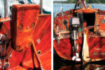
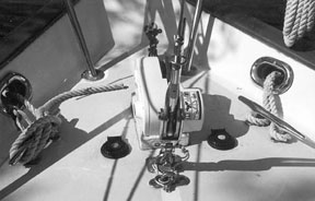
Small footprint
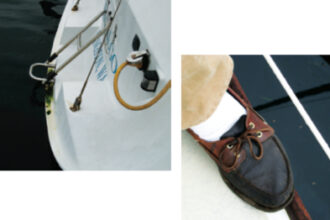
When the windlass arrived I was impressed with its small footprint on the foredeck. I decided to mount it on a 1 1/2-inch pedestal. This would give a better angle of lead for the rode to the bow roller. And it would prevent water on deck from going down into the anchor locker through the chain-pipe hole. I made this pedestal from two thickness of 3/4-inch exterior-grade plywood. I cut two pieces of plywood in the desired rectangular shape and epoxied them together, smooth sides out. I then cut the holes in the pedestal for the chain-pipe hole and for the wire and mounting studs, using the template provided with the windlass. Then I gave the pedestal several coats of epoxy to seal it from moisture. I painted it white to match the paint on the topsides and made a Sunbrella cover for it which was attached to the pedestal with snaps.
Using the template furnished with the windlass, I marked the deck for the holes for the mounting studs, wires, and the chain pipe. I drilled the holes and then cut the chain-pipe hole with a hole saw and saber saw. I covered the holes from below with duct tape. I mixed a small amount of epoxy resin and filled the holes with it. I liberally painted the edges of the chain-pipe hole with this mixture. After allowing the mixture time to thoroughly saturate the edges of the holes, I removed the duct tape and caught the excess mixture in a disposable cup. This is to ensure that moisture won’t get into the core of the deck, saturate it, and cause delamination. I positioned the pedestal and windlass over the holes to make sure everything lined up correctly with the studs and wires through the holes. I placed strips of masking tape on the deck around the pedestal.
Final mounting
Then I removed the pedestal and windlass and applied a bead of non-adhesive caulking around the perimeter and holes in the areas under them. I mounted the windlass and pedestal on the deck. Using large backing plates, I attached locknuts to the studs from below in the anchor locker. Back on deck, I cleaned the area around the pedestal of excess caulking and removed the masking tape. The windlass was ready to be wired.
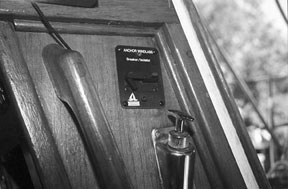
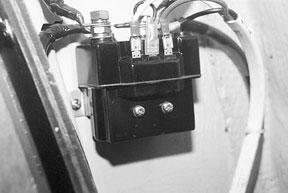
A 50-amp circuit breaker and an up/down toggle switch was included with the windlass. The toggle switch would be fine for installation at the helm of a powerboat where clear observation of the foredeck and windlass is possible. However, on a sailboat you need to be on the foredeck during anchoring and to have some means to operate the windlass from there. The most common method is to have foot switches on the foredeck and a reversing relay mounted in a dry accessible place aft. After surveying all possibilities, I mounted the circuit breaker just inside the companionway, adjacent to the controls for starting and stopping the engine. This would offer easy access from the cockpit. This location has access from the rear in a locker that is high and dry and also has room for mounting the reversing relay. I mounted the foot switches on the foredeck on opposite sides of, but adjacent to, the windlass. Once again, I coated the holes with epoxy when mounting the switches.
According to the instructions, the size of the wire needed depended on the current draw and the distance from the windlass to the battery. After measuring several times, I decided that the most direct route for the wiring wound up being between 40 and 45 feet. As the current flow is from the battery to the windlass and return, this length must be doubled. For lengths of 90 feet, the recommend size wire is #4 AWG.
Range of prices
In checking several catalogs for tinned battery cable of this size, I found a wide variance in prices. West Marine listed the wire at $2.39 per foot. Jamestown Distributors in Jamestown, R.I., (800-423-0030 http://www.jamestowndistributors.com) had the same wire at $1.03 per foot. They also had the wire in 50-foot rolls for $43.09. Because I needed 90 feet, and at $1.03 it would cost $92.70 for 90 feet, I purchased two 50-foot rolls, one of black and one of red, for a total cost of $86.18. This would give me a margin of error in my calculations and a savings in price as well. (The Jamestown wire quoted is SAE wire, while the West Marine wire is AWG. The SAE wire has less copper and a lower theoretical ampacity for a given length. This must be considered in any calculations but may be quite acceptable depending upon actual requrements. -Ed.)
I also purchased some #4 copper terminals to be swaged on the cable for connecting to the battery and other terminals. I swaged these with my Nicopress tool and heated them with a propane torch until rosin-core solder flowed into each terminal. Then I covered each terminal with a piece of heat-shrink tubing.
I ran and connected the shorter lengths of cable: a red cable from the positive battery post to the circuit breaker and then to the reversing relay, and the black negative cable to the engine block and to the reversing relay. It could have been connected to the negative post of the engine-starting battery, but that would have required an additional 6 feet of cable. The run of wire for the foot switches required a three-conductor cable of 16- to 18-gauge wire, as they only carry the current of the reversing-relay coils. I then routed the wiring from the reversing relay to the anchor locker, taking care that the wires were not damaged and stayed clear of the bilge as they were routed forward. I was able to bring the wiring from the windlass and foot switches back from the anchor locker into the V-berth area behind a panel in the overhead. This enabled the final connections to be made in a relatively dry area.
Reversed switches
I connected the heavy battery cables to the windlass wires with copper split-nut connectors. Then I covered these with electrical tape and then with friction tape for abrasion protection and a final wrapping with plastic electrical tape. The foot-switch wires were connected with crimped connectors and covered with heat-shrink tubing.
When it came time to turn the circuit breaker on and try the foot switches, I discovered that the switches were reversed. It was a 50-50 proposition, so I wasn’t surprised. I swapped the switch wires at the reversing-relay coil connections.
I needed to splice my 1/2-inch, three-strand nylon rode to the 20 feet of 1/4-inch high-test chain I had bought to replace the 5/16-inch proof chain I had been using. Although the 1/4-inch high-test chain is smaller and lighter than the proof 5/16-inch, it is much stronger: it has a working strength of 2,600 pounds, compared with 1,900 pounds.
This splice was not as hard as I had imagined it. Anyone who has made “eye splices” on docklines or around thimbles will have no problem completing this splice. About a foot of the three-strand is unlaid and two strands are fed through the last link of the chain while the third strand is fed through the same link in the opposite direction. The strands are back spliced with five tucks and then tapered for several more tucks. At the end the splice is whipped for a finished look. The splice runs through the gypsy smoothly and without hesitation. A customer service representative from Simpson-Lawrence told me that tests have shown that a splice of this type is as strong as either the chain or the three strand. However, I intend to check it frequently for signs of chafe and wear.
How does the windlass work? So far, I have been well pleased with the project and ease of operation. The anchor goes down and back up much faster than I had anticipated. I feel that it has been a very worthwhile addition to the boat. I know my back will appreciate it.
Article from Good Old Boat magazine, July/August 2000.