Summary of Testing Crip Splices
After reading Gord May’s article (“Ohm’s law and You” published in the March/April 2002 edition of Good Old Boat magazine), I was concerned about the high resistance splices he mentioned. These were “old” splices which he said could have a resistance of as much as .01 to .03 Ohms per splice. I’ve seen old wiring from boats in salt water service where the wire had disintegrated completely and the splice fell apart in my hands. Having seen splices turn to powder, I had reason to believe that such high resistance splices might actually exist.
On the other hand, I’ve used hardware store crimp connectors crimped with non ratcheting crimpers on our boat for about a decade. I sealed the ones exposed to the elements with a vinyl sealant, but not the ones that are located in “dry” places. This level of wiring quality has served acceptably. I’ve seen no corrosion, and had no failures in this (fresh water) service. Still I was not measuring the voltage drop across these connections, and did not really know what kind of losses the splices were introducing into the circuit.
I had always made the assumption that a typical crimp splice would have about the same resistance as the wire it replaced, maybe even a little bit less. I also thought that a crimp that had .03 Ohms of resistance might run pretty hot, which would cause its own problems.
The Test
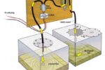
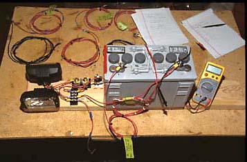 Test setup puts samples in series with two lights and a battery.
I made up nine wire assemblies and tested them before and after spending 100 hours in a corrosive hot salt bath, which was meant to simulate several years in ocean service. We tested tinned vs. untinned wire, hardware store vs. marine grade terminals, ratcheting vs non-ratcheting (cheap) crimping tools, dressing the wire ends with Vaseline, before crimping them vs leaving them bare, sealing terminals with adhesive lined heat shrink tubing, vs sealing the terminals with liquid vinyl “liquid electrical tape” vs not sealing them at all. The test method involved making nine butt splices in a test wire of a controlled length, subjecting it to a controlled load, and measuring the voltage drop across the test assembly before and after subjecting it to a 100 hour 165 degree F salt bath. Finally, the voltage drop across the test wire was used to calculate (Ohms law again) the average resistance of the individual crimps, two per butt splice, 18 total.
 Top wire was protected by Vaseline during the 100 hour corrosion test, bottom wire was not coated with Vaseline and corroded visibly.
The various methods, materials and tools yielded measurably different results:
- The ratcheting crimp tool was so much better than the non-ratcheting crimper that I will never make another crimp with the cheap non-ratcheting crimper.
- Ancor “marine grade” terminals clearly outperformed the cheaper GB (Gardner Bender) terminals.
- Dressing the wires with Vaseline before crimping did not increase the resistance of the splice, and did offer some corrosion protection.
The splices made with adhesive lined heat shrink tubing did not perform significantly better than splices sealed with the liquid vinyl, and in fact the sealed samples did not perform that much better than the unsealed sample in the corrosion test. The fact that all of those samples were made with tinned wire may have made the effects of sealing the terminals difficult to see.
While there were measurable differences between these samples, there were no significant differences between most of the methods tools and materials used.
The Best
Samples made using the best of these alternatives had the same characteristics as unspliced wire, even after the salt bath exposure. If you want a good splice use ratcheting crimpers, tinned wire and marine grade terminals. Dress the wires after stripping and before crimping with an anticorrosion material or Vaseline. Seal the crimp with liquid vinyl or other means.
The worst
 The worst sample got hot enough to suggest that it might cause a fire if it did not have free air circulating around it.
The sample made from untinned wire, not dressed with Vaseline before the crimps, and having cheap GB terminals made with a cheap non-ratcheting crimper and with unsealed splices was significantly worse then all others. (A combination of the low end of all the alternatives.) This sample began to deteriorate as soon as it was made, having a noticeably higher resistance from the start, It went downhill from there, even during the time it spent in a (relatively) clean dry basement before the corrosion test. After the corrosion test this sample ran hot in the voltage drop test, which takes only a few seconds.
We got out a collection of fire extinguishers and energized this combination of the low end alternatives for 30 minutes while measuring the surface temperature of two of the splices. The temperature of the hotter one peaked at 235 degrees F, and then dropped back to 230 degrees F and stabilized. The sample was in open air, not a confined space, nor bundled in with other wires, and it was only carrying about two thirds of the current the wire was rated for. At full current, bundled with other wires, or in a confined space it would have gotten hotter. Perhaps hot enough to cause a fire.
Conclusion
In my opinion most of the practices recommended in Gord May’s article were verified in these tests. Ratcheting crimpers are clearly superior. Ancor marine grade butt splices (both types) are clearly superior to GB butt splices. Tinned wire resisted corrosion better than untinned wire. Sealing the splices did not show much better in these tests, but it is probably a fault of the tests, not a fault of the practice.
Most test samples did not have a significant resistance in the butt splices before or after the corrosion test.
The one with the worst of all the possible choices did have a significant resistance in the butt splices. This test assembly had an average resistance per crimp of about .0003 Ohms when first made. The resistance eventually reached .014 Ohms at the end of the 30 minute test. Interestingly, that resistance is right in the middle of the range that Gord May predicted in his article for a worst case splice.
In my opinion the worst of the samples could cause a fire in a boat without ever blowing a fuse.
Thanks Gord. I’ve learned a lot from all this.
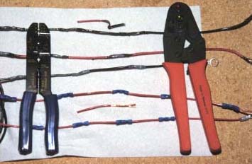 Non-ratcheting crimper on the left, ratcheting on the right. The ratcheting crimper was only marked for metric wire, but worked very well. I have to hope that the non-ratcheting crimper I’ve used on my boat for the last ten years works much better than the one used in these tests.
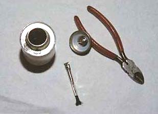 Cut off the brush in the cap of the liquid vinyl can unless you want to paint a fence with this stuff. Just about anything else you dip in there will be less messy. Once you eliminate the mess the cap will seal, and the goop will last longer.
What follows is dry as toast. There is no way to make a detailed description of a test like this one all that interesting. You might want to read on if you intend to argue with the conclusions made in the summary, or if you wish to replicate the test, or just criticize it. Otherwise what follows is likely to put you to sleep. (Sorry)
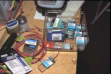
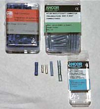
Materials used
- Tinned and untinned wire
- Ratcheting crimpers and non-ratcheting crimpers
- Marine splices, and hardware store splices
- Two methods for sealing connections, adhesive lined shrink tubing, and liquid vinyl sealant
- 14 gauge (AWM, not SAE) wire was used for all tests. Some of the wire was Ancor 14 AWG (UL) boat cable, and some was 14 AWG THHN machine tool wire. The boat cable was tinned, the machine tool wire was not tinned.
- Three types of splices were used. GB (Gardner Bender) splices were obtained from the local farm store, and Ancor nylon insulated butt connectors and heat shrink butt connectors were purchased at the local marine store.
- “Liquid Electrical Tape” was used to seal some samples. This liquid dries to a soft flexible vinyl coating which can be used to waterproof electrical connections.
- Two crimpers were purchased at the local marine store. One was a ratcheting crimper and one was a non ratcheting crimper. All wires were stripped with a new tool also from the marine store.
Test samples
Nine wire assemblies were made. All types were 107.25 inches long, and had a ring terminal at each end. Samples were made with both types of wire. Some samples had only the the end terminals (used for reference), and others had nine additional butt splices. Test assemblies were made using GB splices, as well as with two types of Ancor splices, (one with an adhesive lined shrink tubing, and one without this feature).
List of Samples (all with end terminals)
- Red boat wire, tinned, only end terminals attached with a ratcheting crimper.
- Black boat wire, tinned, only end terminals attached with a ratcheting crimper.
- Tool wire, not tinned, only end terminals used attached with a ratcheting crimper.
- Tool wire, not tinned, with 9 GB butt splices crimped with a non ratcheting crimper.
- Tool wire, not tinned, with 9 GB butt splices crimped with a ratcheting crimper.
- Tool wire, not tinned, with 9 Ancor nylon insulated butt splices crimped with ratcheting crimper.
Note: samples G, H, I had the stripped wire ends dressed with Vaseline before the crimps were assembled. - Black boat wire, tinned, with 9 Ancor heat shrink butt splices also vinyl sealed.
- Red boat wire, tinned, with 9 Ancor nylon butt splices sealed with vinyl only.
- Red boat wire, tinned, with 9 Ancor nylon butt splices not sealed at all.
Red and black wires had the same physical properties, the colors were noted to help keep the various samples straight. All wires were 14 ga., but the tool wire had coarser stranding and was not tinned.
Test methods
The wire assemblies were tested by putting them in a circuit with two 55 watt lamps (wired in parallel), a switch, and a type 8G30H gel cell battery. Because it is very difficult to directly measure resistance as low as .03 Ohms, voltage drop was measured across the wires (including the nine butt splices) instead. Each butt splice had two crimps, so the measured voltage drop was across a total of 18 crimps and the remaining wire.
The sections of plain wire used measured a voltage drop of around 212 millivolts with the current in the circuit at 9.2 amps. This corresponds closely to the published resistance of 14 ga. wire.
#14 Wire Specifications:
- .002580 Ohms per foot
- 4110 circular mils cross sectional area
Initial tests
Initial tests were conducted to determine the characteristics of the test apparatus and the general nature of the samples.
In the first series sample A completed one side of the circuit and was compared with samples B and C (wires with only end terminals). In the second series sample C was compared with samples D and E (all tool wire with only end terminals).
Testing with A as the reference
- A – 211.5 mv
- B – 211.9 mv
- A – 211.3 mv
- C – 213.5 mv
Early conclusions were that test/retest of A showed repeatability, and that A, B and C were similar samples. A, B, and C, all with only end terminals tested were roughly equivalent.
Testing with C as a reference
- C – 212.0 mv
- D – 260.3 mv
- C – 212.6 mv
- E – 238.2 mv
Early conclusions were that test/retest of C showed repeatability and that while C was similar to A, (boat wire had about the same resistance as tool wire) the samples D and E had higher resistance.
 General conclusions
It is difficult to explain why the GB splices did not perform as well as the Ancor splices. I removed the insulation from both the measure them. Ancor barrel has more metal in it, and a larger cross section, but both had a greater cross section than the wire.
9 GB butt splices crimped with a ratcheting crimper had a higher resistance than a straight wire of the same length, and 9 GB butt splices crimped with a non ratcheting crimper had even more resistance. This showed the ratcheting crimper to be superior.
The resistance of samples D and E increased over the course of a few days even though they were stored in a clean dry basement.
Conclusion: GB butt splices have more resistance than the wire they replace.
Based on the tests above, samples G, H, and I were constructed. These samples were constructed for testing in the salt bath.
Samples G, H, and I, were all made from tinned wire, all used the superior Ancor crimp connectors, all wire crimped with a ratcheting crimper.
Sample G was built from sample B. (Nine butt splices wire added and the length adjusted to 107.25 inches again.)
Sample G used Ancor butt splices that were heat sealed. Samples H and I used Ancor butt splices that were not designed to be heat sealed. G and H were sealed with vinyl sealant, and sample I was not sealed at all.
All the wires ends in samples G, H, and I were dressed with Vaseline before the crimps were made. Sample G was double sealed, which is to say, it was heat sealed and then sealed with liquid vinyl. All available samples were then tested for connection resistance one more time before salt bath testing:
TESTING BEFORE SALT BATH
- A – Reference
- B – 211.5 mv
- C – 214.1 mv
- D – 277.3 mv
- E – 266.8 mv
- F – 222.8 mv
- G – 209.7 mv
- H – 205.7 mv
- I – 208.1 mv
Note that the resistance of samples D and E had increased over previous test results. Also note that the resistance of samples G, H, I were slightly less than unspliced wire. (Data for B was taken and then it was made into sample G).
Conclusions: The last three test assemblies were able to achieve a quality level such that they were at least as good as plain wire. Samples D and E degraded in very benign conditions.
Salt bath testing
The salt bath test was intended to be similar to the Salt Spray Test (ASTM B117). Correspondence will not be exact, only rough. The samples were put into a domestic food slow-cooker operating at 165 degrees F, with a 5% (by weight) salt water solution in the bottom. The samples were held out of the water by sections of HDPE plastic in the bottom of the cooker. The samples were exposed to this salt bath for 100 hours. A small piece of bare untinned wire was also included in the test. It discolored badly indicating that the salt bath test was effective in causing significant corrosion in 100 hours.
Observations: All the exposed tinned terminals corroded to a gray/black color but did not corrode enough to show the blue/green color of copper corrosion.
Samples G, H, and I were tested after the salt bath exposure. All end terminals were wire brushed and coated with Vaseline to eliminate end terminal resistance caused by corrosion. Samples D and E were NOT in the salt bath, only G, H, I. Despite this, samples D and E degraded more than G, H, and I.
Post salt bath test
- A – 210.7 mv
- B – 209.8 mv
- A – 212.7 mv
- H – 214.5 mv
- A – 213.0 mv
- I – 212.1 mv
- A – 211.8 mv
- D – 362.0 mv
- A – 212.1 mv
- E – 262.3 mv
Accuracy Limitations: Sample A was observed to have a voltage drop of 210.7 mv to 213 mv at various times during these tests. This 2.3 mv range in readings may be taken as a rough measure of the variability caused by the methods and equipment. Changes within this range may be safely ignored as noise, not data.
Discussion of results
Resistance changes in the samples G, H, I after the salt bath were small enough to be considered insignificant.
Since sample I was not sealed in any way, its performance seems unexpectedly good.
Note that although samples D and E were not tested in the salt bath at this point in the test series, their resistance continued to climb over the course of four days while stored in a clean dry basement.
Next Test
Samples D, E, and F were put in the salt bath for 110 hours. (The extra ten hours were because I forgot to take them out on time.)
Two stripped, untinned wires were also put in the bath, one dressed with Vaseline, and one not.
At the end of the test, the wire that was not coated with Vaseline was not as corroded as the uncoated wire in the previous salt bath test. This suggested that the second bath was not as corrosive as the first bath. Temperature and salinity were about the same, and the time was longer for the second bath so there was no explanation in these three variables. The only difference in the tests was the nature of the insulation of the wires, and the masking tape labels left on the wires in the second test. These variables may or may not have caused the bath to be of a slightly different character, having less corrosive effects. Despite indications that the second test was less corrosive, the samples tested showed signs of serious corrosion.
- A – 198.6 mv
- B – 1477 mv
- A – 208.1 mv
- H – 424 mv
- A – 208.9 mv
- I – 243.4 mv
Note the lower voltage drop for sample A (the control) in some of these tests. Sample A was not losing resistance. The sample it was paired with had so much resistance that the circuit current was reduced.
In the few seconds required to conduct these tests it was obvious that sample D had degraded enough to cause the crimps to get hot. By contrast, all the other wire samples in the tests stayed roughly at room temperature.
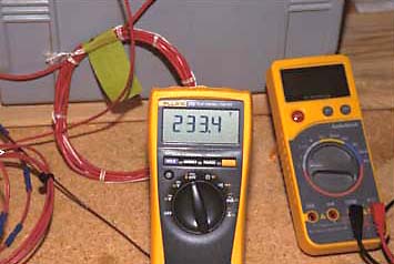
A final test was conducted by energizing sample D for 30 minutes while measuring the surface temperature of two of the butt splices. The temperature of the first of the two splices rose from 67 degrees F to 106 degrees F in the first ten minutes. By this time there was a fragrance of hot plastic coming from the wire, which suggested that some splices were much hotter.
While the test continued the temperature probe was moved to another splice. That splice measured 169 degrees F at 11 minutes. The temperature of that splice peaked at 235 degrees F at 20 minutes, then dropped back to stabilize at about 230 degrees F.
At 18 minutes, the voltage drop of sample A (the other side of the series circuit) was 189.2 mv which suggested that the resistance of sample D was high enough to drag down the circuit current significantly. The voltage drop of sample D at the same time was 2260 mv.
Final conclusion
Gord May suggests that crimp splices can deteriorate to a condition where they have a resistance of .01 to .03 Ohms. This would be quite significant. These tests suggest that the best made splices have virtually no more resistance than wire of the same length, even after salt bath testing. All test samples made with a ratcheting crimper performed reasonably well. The testing did, in a general way, prove the superiority of ratcheting crimpers, tinned wire, Ancor brand crimp connectors, and (probably) dressing wire strands with an anti corrosion coating like Vaseline before assembling the crimp.
Sample D stood out during these tests. It was made with a non-ratcheting crimper, untinned wire, no wire dressing before the crimp, cheap splices, and no sealing after the crimp. It was the worst possible combination of the test variables, and its performance was measurably and significantly worse than all the other samples.
The average resistance of the 18 crimps of sample D progressed as follows:
- As Built – .0003 Ohms
- Aged 4 Days – .0009 Ohms
- After Salt Bath – .0076 Ohms
- 30 min. Test – .0140 Ohms
Note the extreme change in resistance during testing, and also note that sample D did finally reach the middle of the range that Gord May suggested for bad splices.
The testing did not prove the superiority of heat shrink tubing, and showed only a small improvement from even sealing the connections. This is not to say that the value of these measures was disproved. Just that no great difference was seen in this test procedure.
The superior conductivity of the Ancor splices over the GB splices is difficult to explain. The 14 ga.. wire has a cross sectional area of 4110 cm (circular mils) while the GB splice had an area of 12,987 mils, and the Ancor splices had an area of 15,533 mils. The Ancor splice is a little heftier, but both splices have a much more area than the wire. Some other characteristic must determine why one performed better than the other.
The wire stripper used for these tests was of a new and novel design. In this design there are no “dies” sized to cut around the wire. The wire is simply gripped top and bottom and torn apart. The stripper was purchased at a marine store, but later we saw them at a lower prices at K-Mart and a builder’s store. The stripper did a good job in most cases but did drag strands out of short wires already cut from the roll. It is not a perfect tool, and another kind of stripper should be kept available for stripping short wires so that copper strands will not be dragged out of the insulation.
Critique of the test apparatus and methods
 Slow cooker was used for salt bath testing. Not per ASTM specification.
In the apparatus used the voltage and current were slowly but constantly falling throughout the test, with a spontaneous recovery of the battery voltage between test sessions. Although the VOM used could read to .01 amps, that digit was constantly dropping as the battery discharged. A constant voltage power supply would stabilize this variable and allow more accuracy.
Copper wire resistance changes with temperature. If the test used a constant voltage power supply, wire temperature would be the next place to look for inaccuracy.
Sample D eventually had a significant enough resistance to change the circuit current and distort the results. This was compensated for by deriving the new circuit current from observing the voltage drop in the sample wire it was paired with. Resistance calculations were altered to correct for this change in current.
It was felt that these electrical distortions did not invalidate the tests because small variations were not needed to support the conclusions reached.
The salt bath test was constructed along the lines of the Salt Spray Test (ASTM B117) salt spray specification, however the slow cooker, at less than $20 was not a good substitute for an Salt Spray Test (ASTM B117) test machine.
Critique of test logic
The problem with almost any test is that it must make a logical connection with reality. In most cases reality is so highly variable that in tests run outside the controlled conditions of a laboratory, extremely large samples are required, and extremely large periods of time are also required. Even given these, it is often difficult to make a strong cause and effect case, which is to say, the determining variables may be inferred, but rarely identified without doubt.
This testing relied on a simplified hot salt water exposure test to produce corrosion. Engineering and industry have been using the Salt Spray Test (ASTM B117) for a long time, but have not been able to equate it to any set of actual service conditions.
In the case of the salt spray test made from a slow cooker, only the time, temperature and initial salinity were the same as the ASTM B117. As water evaporated, it was replaced with more water of the same salinity, and by this action, the salinity of the bath could only go up. It is estimated that the end-point salinity was nearer 10% by weight.
City water was used, which is known to be chlorinated. All that may be said of the salt bath used is that it corroded untinned copper wire about as would be expected.
Any accelerated test tends to have problems correlating to actual field conditions because to accelerate the test, extremes are used. For example, higher temperature is substituted for longer time.
Final comments
The tests did produce one sample with an average crimp resistance of .014 Ohms which was right in the middle of the range that May predicted (.01 to .03 Ohms).
In the case of this worst case sample, which used a non-ratcheting crimper, and lower quality butt splices, no anticorrosive treatment, and no sealing of the splices, the tests suggest that such methods can produce connections which will be dangerous, possibly causing fires.