
 Follow up on Installing a Chart Plotter at the Binnacle, from our May 2013 Issue.
When I decided to subscribe to a satellite weather service (XM WX Satellite Weather), I found that a simple connection into my existing chart plotter was not on the cards. I ended up fitting a new chart plotter that uses the NMEA 2000 network standard, but I had to connect some other devices to it that use the NMEA 0183 standard.
In the May 2013 issue of Good Old Boat I described some of the issues I faced but did not go into the details of the installation. For good old boaters thinking about undertaking a similar project, this summary of the work I did to install a newer model chart plotter on the binnacle guard of our J/32 might provide an idea of what to expect. Even though the installation was relatively straightforward, it took longer and required me to address more issues than I expected.
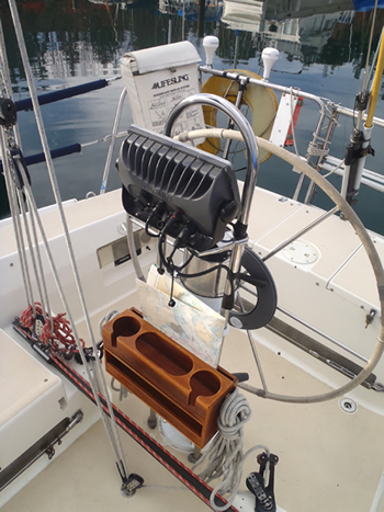
The carrier bar for the chart plotter is mounted on stainless-steel arms clamped to the binnacle
The binnacle mount
The first issue had to do with mounting the new chart plotter and running the required cables to it. Our old chart plotter was mounted on a shelf clamped to the tubular binnacle guard. The shelf was cast aluminum with a white powder-coat finish. As it was showing signs of corrosion, I decided to replace it. When I called Edson, the customer-service guy told me it is no longer manufactured, and suggested I consider a pair of 7-inch stainless-steel arms that clamp to the tubes of the binnacle guard.
I followed his advice, but needed to cut a couple of inches off the arms. To match the original fine finish, I sanded and polished the cut ends. These arms will fit tubing up to 1 1/4 inch in diameter and came with plastic inserts that allow them to be secured to 1 1/8-inch or 1-inch tubes. Our binnacle-guard tubing is 1 inch in diameter, so I used both inserts. I found that, even with the arm clamp fully tightened, the arms could be easily slid along the tubes. My solution was to wrap vinyl electrical tape around the tubing to provide a better grip for the plastic insert.
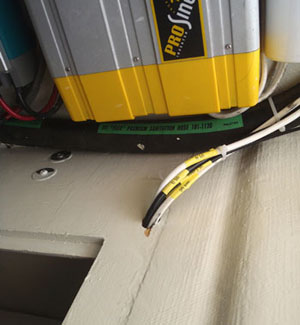
The extension cables lead from the fuel-tank compartment to a terminal strip behind the power panel
Cables to the chart plotter
The next job was to run the associated cables to the new chart plotter. The old Garmin GPSMAP 3206 combined the NMEA 0183 wires, GPS antenna wires, and power supply in a single cable. This cable came up from below the cockpit sole inside the binnacle-guard tubing and exited through a hole cut in the tubing near the original shelf location.
The new chart plotter uses three cables, one for NMEA 0183 ports, a dedicated power cable, and an NMEA 2000 cable. Fortunately, the boat’s first owner had installed pod-mounted sailing instruments (that I had previously relocated to the sea hood). I was able to reuse their cables’ holes and didn’t have to cut more. (Although it’s common practice to run cables through the binnacle guard, too many holes in the wrong locations could weaken the the tubing.)
Running more than one cable through a tube can complicate life for the installer, particularly if any of the cables have molded end fittings that must be retained. In my case, the NMEA 2000 drop cable had molded fittings at each end, and I had to enlarge the hole in the wall of the tube to accommodate it. I also trimmed down the molded fitting as much as I could without compromising its function. (After-market end fittings are available that can be mechanically secured to the cut end of an NMEA 2000 cable if necessary.)
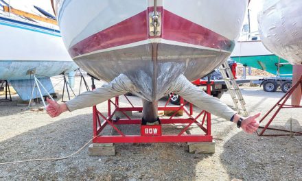
A 27-gallon fuel tank occupies most of the compartment below the cockpit sole of our J/32. With a little body contortion, it’s possible to access the bottom ends of both binnacle guard tubes.
The next challenge was running the chart plotter’s cables to where they need to go. It is almost certain that the cables supplied with the chart plotter will not be long enough. I had to extend the power and NMEA 0183 cables from the fuel tank compartment into the space behind the power panel above our nav table. The supplied cables were about 6 feet long. The run through lockers and into the space behind the power panel required a 12-foot extension.
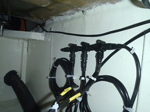
The NMEA 2000 backbone has three drop cables teed into it
Extending the power cable was easy, since I had a good supply of marine-grade 14-gauge 2-wire cable. Crimp connectors work well with wires of this gauge.
The NMEA 0183 cable was another matter. This cable contained a total of 19 wires of about 24 gauge each. The wire complement included eight wires for the four receive ports, four wires for the two transmit ports, a ground wire, plus two wires for use with the old-style GPS antenna, an accessory wire, a wire to drive an external alarm, and two spares. I could not locate a ready source for 19-wire cables with fine-gauge wire, so I organized the extension into three parts. I purchased a length of 8-wire instrument cable with 20-gauge wires and used this for the four receive channels. In my stock of spares, I had two suitable lengths of shielded 4-wire cable with 24-gauge wires. I used one length for the two transmit channels and the other for the ground wire, the two GPS antenna wires, and the alarm output wire.
The Garmin installation manual strongly recommends soldering extension wires for the fine wires in this cable because crimp fittings do not work well on fine wires. I had to splice all these fine wires while sitting in the port cockpit locker and leaning through the access hole into the space below the cockpit sole that is largely filled with the fuel tank. I spent far too many hours in that cramped location with a soldering gun, wire cutters, heat-shrink tubing, a barbecue lighter, and 3M electrical tape. But, finally, all the splicing was done and I secured the cables to the locker wall with screw-mounted wire ties.
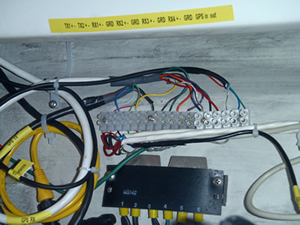
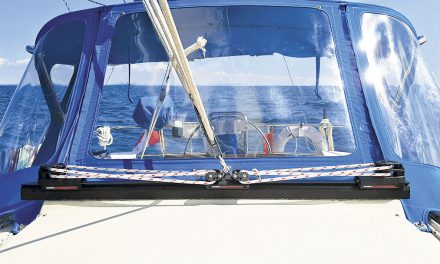
The NMEA 0183 terminal strip has 18 connectors
More tedious work remained to be done behind the power panel. I mounted a sufficient length of terminal strip to accommodate the four receive ports, the two transmit ports, ground wire(s), and the two wires for the old-style GPS antenna. (I am not using an external alarm so that wire is taped off.) I then had to connect the NMEA 0183 wires from existing devices to the appropriate points on the terminal strip. These included input and output from the AIS receiver, input and output from the DSC-capable VHF radio, receive only for the TackTick sailing instruments, and receive only for the autopilot. This step required some care since the NMEA 0183 standard allows for double-ended inputs — both a plus (+) and a minus (-) wire for each port — whereas many devices (including all of mine) choose a single-ended implementation that uses just the plus (+) wire referenced to the system ground. Wiring diagrams in the Garmin instruction manual covered this point with care. (We use Garmin chart plotters on Sirius, in part because the first owner of our boat had installed one. Many fine choices are available today and the major steps for installing a chart plotter should be the same regardless of the brand. I hope other instruction manuals also provide the same clear guidance.)
The usual rule of thumb is that a “talker” has sufficient power to drive three “listeners.” Connecting more than three listeners may cause the network to fail. If an installation needs to reliably feed four or more listeners, a buffer-amplifier should be installed between the talker and the listeners.
The two photos show the stark differences between the two network standards. The NMEA 2000 backbone, secured to the wall of the fuel tank compartment under the cockpit sole, has three drop cables teed into it for the GXM 51 satellite weather receiver, the Garmin GPS antenna, and the chart plotter. I led the other end of the backbone behind the power panel above the nav station, where I supplied power through another tee. Extending the backbone to this location makes it readily accessible for future electronic upgrades.
The terminal strip is for the NMEA 0183 ports (two transmit and four receive for the new chart plotter). The four existing devices on our boat that communicate via NMEA 0183 networks are connected to appropriate terminals.
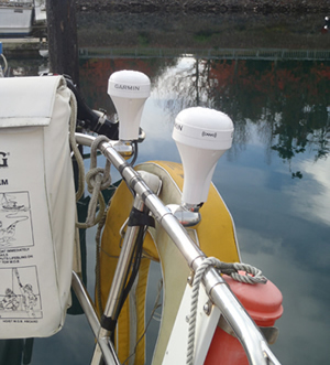
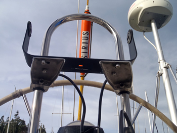
The antennas for the GPS and the GXM 51 satellite receiver are mounted on the stern rail
Antennas and deck fittings
Next, I addressed the installation of the new GPS antenna. I could have used the original antenna. However, I decided to use the new NMEA 2000-compatible unit included with the new chart plotter. The diameter of the NMEA 2000 drop cable was larger than that of the cable for the old antenna. More important, it was too large for the existing through-deck fitting, so I had to upgrade the deck fitting.
I used a similar deck fitting to feed the cables from the GXM 51 satellite receiver. This unit can receive both WX Satellite Weather and XM Satellite Radio. (We have only subscribed to the weather service, but retained the radio cable for possible future use.)
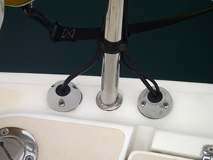
The antenna cables enter the boat through fittings on the stern
The marine electronics industry is in an awkward transition between the older and the newer network standards. I imagine many sailors, like me, have an installed base of devices that use NMEA 0183 and are planning to add new devices that require NMEA 2000. Someone thinking about installing only electronic devices that require a network might be able to avoid these complications and just go with NMEA 2000.